Planning the Class IV: The Workhorse of Cosmetic Dentistry — Part 1
By Jason Smithson on July 23, 2021 | commentsPart 1 of a series of articles exploring the esthetics of a Class IV direct composite restoration.
The Class IV
To understand all the approaches to resin anterior dentition, you must first comprehend the preparation, layering, and finishing protocols behind Class IV direct composite restorations. The reason being all anterior direct restorations are a variation on Class IV. For example:
- A resin veneer is a minimally invasive Class IV that extends to the gingival margin.
- A resin veneer for a discolored tooth is a minimally invasive Class IV that extends to the gingival margin, which employs an opaquer dentin layer to mask the discoloration.
- Diastema closure is a Class IV mesioincisal (MI) restoration on one central incisor with the same restoration on its opposite number.
- A peg lateral restoration is a MI direct and a distoincisal (DI) direct Class IV on the same tooth.
Therefore, if you have a clear command of the Class IV restoration, you can confidently approach any anterior situation with direct resin.
Palatal Shells
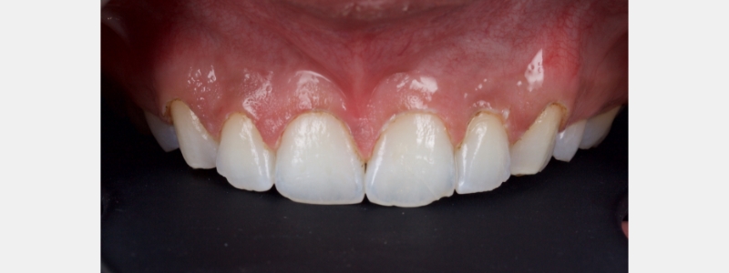
A diagnosis of altered passive eruption (APE) alongside tooth surface loss (TSL) secondary to parafunction was made for a referred female patient in her early 20s who complained of having, “short, fat, baby teeth.” Due to her age, she was treated with a simple gingivectomy (after bone sounding), nightguard vital bleaching (NGVB), and additive edge-bonding.


The worn incisal edges were restored with edge bonding, a new technique for restoration of worn dentition, which should be regarded as a multiple Class IV restoration.


Planning and the Palatal Stent
All cases used the Facially Generated Treatment Planning concepts utilizing maxillary incisal edge display with lip at rest as a guide.
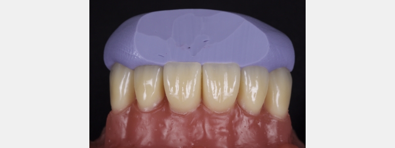
In most cases, the composite resin is layered using a polyvinyl siloxane (PVS) palatal stent. Layering allows accurate control from palatal to facial, and it reduces the need for significant post-op occlusal adjustment.
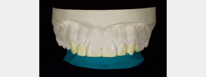
A palatal PVS stent is fabricated from a mock-up of the anticipated outcome. This can be done in one of three ways:
A palatal impression is taken in the patient's mouth using the patient's existing incisal edge position and tooth morphology. The aim is to reproduce the existing morphology and tooth length.
This approach is usually employed when replacing existing resin restorations, which are esthetically and occlusally acceptable from a morphological point of view but perhaps require replacement due to marginal breakdown or unacceptable loss of surface polish.
Intraoral mock-up. Without etching or bonding the teeth, build the teeth to the desired length with direct composite resin. Then the resin is refined with burrs/discs, and the occlusal scheme is verified.
Take a simple PVS palatal impression of the palatal surfaces. The mock-up is removed with a sickle scaler and the stent is used to layer the final restorations. This approach is useful if a single visit appointment is required and there is no time for models or a diagnostic wax-up. For example, in the immediate treatment of fractured teeth because of trauma.
- Impressions and a diagnostic mock-up. This can be done with alginate impressions, stone models, and hand waxing or digitally (scanned impressions, CAD mock-up, and 3D printed models). I prefer digital for simple cases and analog for those that require significant occlusal changes (e.g., increasing the occlusal vertical dimension).

When fabricating the stent, always cover at least six teeth to give a degree of cross-arch bracing to stabilize the stent in the mouth while layering. Stents that cover fewer teeth often rock in use, which can result in an inaccurate reproduction of the mock-up.
The stent should always extend one tooth beyond the terminal tooth to be treated. Extending further does not confer an advantage since it often results in seating issues.
I prefer a PVS putty, which is high contrast in color. For example, blue, green, or purple rather than beige or pink. PVS putty improves visualization when placing the initial composite shell.
Oftentimes, when fabricating the stent, it will extend onto the facial surface resulting in access issues when layering. Instead, simply trim the stent with a sharp blade such as an 11 scalpel or a simple carpet knife. The trim should be through the incisal edge midway between the facial and palatal surfaces. The angle of trim should mirror the inciso-facial surface of the tooth to be restored.


After a stent has been successfully fabricated, the next dilemma is determining how much resin the stent needs to create the resin palatal shell.
Too much resin results in significant interproximal excess, wasted time in removing the excess resin, and patient discomfort. Too little resin often fails to form a continuous union between the shell and the tooth. Consequently, when the stent is removed the shell tends to break.
The solution is simple. After tooth preparation and before bonding, apply the stent to the tooth intraorally (Fig. 20).

A thin, sharp, flat plastic is run along the fracture line to create a fine score on the PVS stent (Fig. 21).

It is important the score is minimal and does not gouge. Deep gouging tends to create PVS debris and can be erroneously incorporated into the final restoration (Fig. 22).

The achromatic resin used to create the shell is then layered on the stent 2 mm apically beyond the score line. In my experience, this is the sweet spot for how much resin to apply.
Another often overlooked diagnostic stage is the direct preview, which is helpful if significant morphological changes are planned, and the patient is discerning. This is useful for both direct composite and indirect ceramics and allows you to assess esthetics, phonetics, and occlusion.
I tend to use the indirect-direct approach whereby a diagnostic mock-up is fabricated indirectly. Then a stent is made of the mock-up both facially and palatally using a clear PVS (e.g., Memosil [Kulzer], RSVP [Cosmedent], or Exaclear [GC]). The stent is filled with flowable composite and seated in the patient's mouth (it is important not to apply any bond). The resin is polymerized, and the stent is removed. This allows both you and the patient to visualize the result, which is a more powerful patient communication tool than a diagnostic wax-up in this respect.
In this case, a young patient in his early 20s presents with discolored central incisors, multiple diastemas, and a canted incisal plane (Fig. 23).

A clear PVS stent was fabricated from a digital wax-up and filled with flowable composite (Fig. 24).

I prefer an opaque flowable composite for this application because regular flowable composite tends to be quite translucent making the underlying tooth structure visible, which distracts many patients. The flowable composite was polymerized and the stent was removed.
The esthetics were assessed by the patient and some adjustments were made to the distal line angles of the lateral incisors. When the patient was satisfied with the appearance another sectional digital scan was taken of the modified mock-up in the patient's mouth and stitched into the original scan to form the final mock-up (Figs. 25 & 26).


The next article in this series will focus on layering stages. Read “Finishing Anterior Composite: How to Recreate Natural Enamel Morphology and Texture” to learn about the polishing protocol.
Jason Smithson, BDS (Lond), DipRestDentRCS (Eng), is a member of Spear Resident Faculty.
References
- Dolt, A. H., Robbins, J. W. (1997). Altered passive eruption: an etiology of short clinical crowns. Quintessence International, 28(6).
- Kan, J. Y., Kim, Y. J., Rungcharassaeng, K., Kois, J. C. (2017). Accuracy of Bone Sounding in Assessing Facial Osseous-Gingival Tissue Relationship in Maxillary Anterior Teeth. International Journal of Periodontics Restorative Dentistry, 37(3).
- Haywood, V. B. (1997). Nightguard vital bleaching: current concepts and research. The Journal of the American Dental Association, 128, 19S-25S.
- Dietschi, D. (1995). Free-hand composite resin restorations: a key to anterior aesthetics. Practical periodontics and aesthetic dentistry: PPAD, 7(7), 15-25.
- Spear, F. (2016). Diagnosing and treatment planning inadequate tooth display. British Dental Journal, 221(8), 463-472.
- Vig, R. G., Brundo, G. C. (1978). The kinetics of anterior tooth display. The Journal of Prosthetic Dentistry, 39(5), 502-504.